Heathkit SB220 refurbishment project.
I decided to have a closer look and take on the challenge of refurbishing her.
First thing to do
removal of the chassis enclosure
Wow
.. indeed she has fallen from some height.
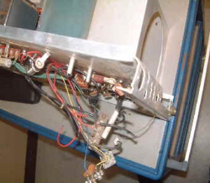
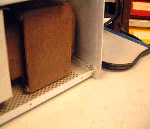
The right rear corner completely broken .Due to the transformer weight de chassis was completely deformed. Both circuit breakers fully smashed!
The long term storage in a sea container
and the humid conditions in the Caribbean took her toll as well.
Most of the parts where badly corroded, both the transformers red from rust, and after the removal of the HV transformer it looked if she made some water in the past.
![]()
Humidity and sea water can take their toll.
A closer inspection of her chassis parts and wiring became necessary . And my final conclusion was to strip her down to the bone Hi
One of the main reasons to strip the wiring as well was given by the fact that the builder those days used small soldering-iron
something like 15 or 20 Watts and all thick wires had poor
cold soldering points.
I found several modifications like a slow start or inrush protection on the filament transformer.
Searching the internet I found more than once that this was a useless modification as the filament transformer him self protects the inrush current.
Another modification I found was a reducement of the cooling fan speed
by the use of an resistor.
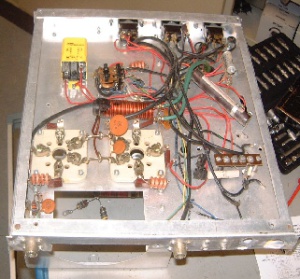
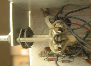
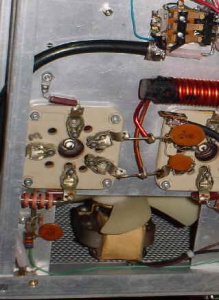
This how she looked before, most of the previous wiring intact. But as it shows quit chaotic
.!
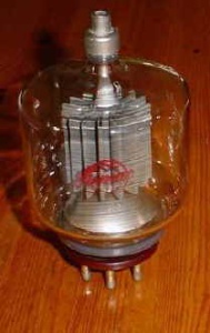
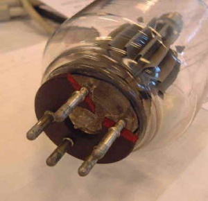
I also tested the Eimac 3-500z tube’s
one of them had some suspicious marks. Hi But both tubes seems to be okay
tested by PA5R in his SB1000, the only thing he found was a big difference on 10M the load and plate tuning was completely different.
I glued the retainer, most of it was still there so I do not expect problems there.
Thanks to Herman PA0TEN, he replaced the broken band-switch, the one he used is from a superior quality . Better than the original one.
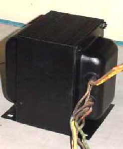
Both transformers needed a firm scrub and new paint.. noticed the difference!!! ??.
![]()

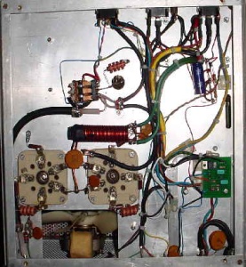
Gradually I started the rebuild and assembly. All the wiring was brought back to almost the original state. Partially I had to replaced wiring due to the poor condition.
Previously the builder chose to use RG58 from the relay to the output connector, I replaced that by RG213.
The coax used for the input and driving the tubes where replaced by special RG58 double shielded.
Main switches where reconnected, I crimped special SS steel AMP sleeve connectors to all wire terminals.
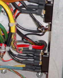
Here a closer look at the RG214 cable, from the relay to TX output.
Here you can see the differences between the previous and new wiring.
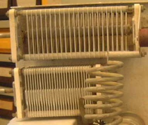
The “Loading and Tune” capacitors caused me some worry… they both where corroded and need a firm clean up.
I have been working on them for a whole evening, the result looked promising.
So after many long hours I finally managed to complete the assembly, now the real challenge began, adding the juice….
I started with a variac transformer… in that way I had control over the main voltage… gradually I increased the mains from zero to about 50 Volts… in the mean while I closely monitored the filament voltage… just to be sure I wired the transformer okay. Al seem to be okay.
I knew that the rectifying capacitors may go wrong because this is the first time they become charged after a long period… so gradually I increased the voltage up to 230 Volt.
Filament voltage without the two tubes showed 5,25 Volt… and the HV meter showed 2800 Volt.
That was promising.. sure… now the same challenge with the two 3-500Z’s installed, as I increased the voltage the fan began to spin and the two tubes glow… still monitoring the filament voltage… at 230 Volt mains I measured 4,90 Volt… beautiful. I kept here on the mains for about two hours, HV showed 2700 Volts.. Switched of the mains and it took 30 or more seconds before the capacitors where fully discharged. That gave me the impression that the old capacitors where still functional.
Now the final test… Hi… connected a 1KW dummy load and my Kenwood TS850sat.
After tuning I become high SWR in the input … Mmmmm what did I wrong… simple I wrongly connected the TX – RX relay.. just swap the two connections cured the problem.
I managed to become about 1 Kw on the low bands up to 15M 10 meter was a problem again SWR problems little to high for the 850.. Had to remove the front panel and trim the input coil… SWR now from 1:3 to 1:1.8 much better..
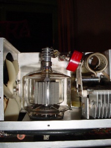
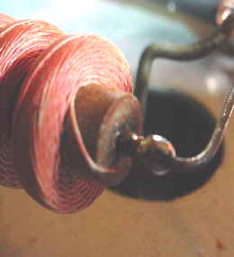
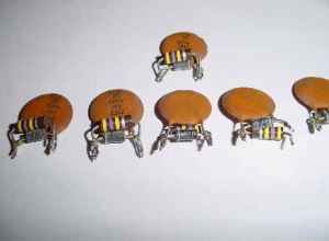
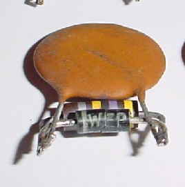
While testing I noticed some sparking between the tuning capacitor… Mmmm bad sign the anode capacitor 1nF 6KV was leaking… and it damaged the RF output choke…. That explain the sparking…
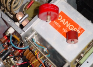
Replaced the anode capacitor 1,5nF at 25KV.. but a little to large… had to modify the bracket…
Little to close to the tube, see my last minute modification, bending the bracket plate.
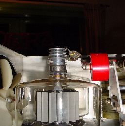
See the difference in size
The repaired RF choke,
After the replacing the anode capacitor and repairing the RF choke I tested her again, now the output measured varying from 1,1KW down to 900 Watts…. Certainly I noticed some rustle… somewhere at the front.. while tuning again I saw some sparks coming from the rectifier board…. The pictures explain why.
Now I had to remove the front panel again and the rectifier board needed to removed in order to replace all the diode rectifiers. So the 1 ampere diodes where replaced by 3 ampere 1000V PIV ones.
At the same time I placed two diodes at the rear of the two panel meters they most likely protect the meters for a reversed current.
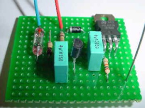
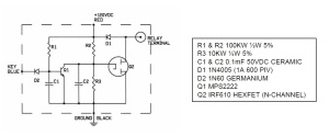
The last few things to do, modify the TX relay control… so I found a nice diagram and build the circuit… works fine with me.
So to complete the refurbishment I need to paint the enclosure, took me some while but I believe I found the correct colour …..
The enclosure is painted now and looks fine.
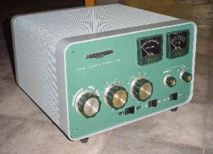
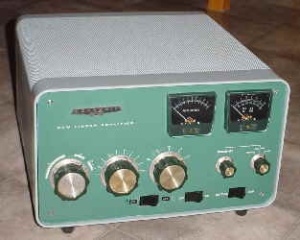
The refurbishing took me almost three weeks, every evening… but I’m happy with the result.
73…. Frans de pa5ca